|
 |
Blobs are described as spheres and cylinders covered with "goo" which stretches to smoothly join them
(see section "Blob").
Ideal for modeling atoms and molecules, blobs are also powerful tools for creating many smooth flowing
"organic" shapes.
A slightly more mathematical way of describing a blob would be to say that it is one object made up of two or more
component pieces. Each piece is really an invisible field of force which starts out at a particular strength and falls
off smoothly to zero at a given radius. Where ever these components overlap in space, their field strength gets added
together (and yes, we can have negative strength which gets subtracted out of the total as well). We could have just
one component in a blob, but except for seeing what it looks like there is little point, since the real beauty of
blobs is the way the components interact with one another.
Let us take a simple example blob to start. Now, in fact there are a couple different types of components but we
will look at them a little later. For the sake of a simple first example, let us just talk about spherical components.
Here is a sample POV-Ray code showing a basic camera, light, and a simple two component blob:
  #include "colors.inc"
  background{White}
  camera {
    angle 15
    location <0,2,-10>
    look_at <0,0,0>
  }
  light_source { <10, 20, -10> color White }
  blob {
    threshold .65
    sphere { <.5,0,0>, .8, 1 pigment {Blue} }
    sphere { <-.5,0,0>,.8, 1 pigment {Pink} }
    finish { phong 1 }
  }
The threshold is simply the overall strength value at which the blob becomes visible. Any points within the blob
where the strength matches the threshold exactly form the surface of the blob shape. Those less than the threshold are outside
and those greater than are inside the blob.
We note that the spherical component looks a lot like a simple sphere object. We have the sphere keyword, the
vector representing the location of the center of the sphere and the float representing the radius of the sphere. But
what is that last float value? That is the individual strength of that component. In a spherical component, that is
how strong the component's field is at the center of the sphere. It will fall off in a linear progression until it
reaches exactly zero at the radius of the sphere.
Before we render this test image, we note that we have given each component a different pigment. POV-Ray allows
blob components to be given separate textures. We have done this here to make it clearer which parts of the blob are
which. We can also texture the whole blob as one, like the finish statement at the end, which applies to all
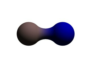
components since it appears at the end, outside of all the components. We render the scene and get a basic kissing
spheres type blob.
The image we see shows the spheres on either side, but they are smoothly joined by that bridge section in the
center. This bridge represents where the two fields overlap, and therefore stay above the threshold for longer than
elsewhere in the blob. If that is not totally clear, we add the following two objects to our scene and re-render. We
note that these are meant to be entered as separate sphere objects, not more components in the blob.
  sphere { <.5,0,0>, .8
    pigment { Yellow transmit .75 }
  }
  sphere { <-.5,0,0>, .8
    pigment { Green transmit .75 }
  }
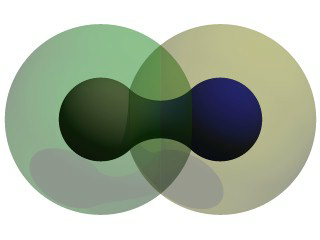
Now the secrets of the kissing spheres are laid bare. These semi-transparent spheres show where the components of
the blob actually are. If we have not worked with blobs before, we might be surprised to see that the spheres we just
added extend way farther out than the spheres that actually show up on the blobs. That of course is because our
spheres have been assigned a starting strength of one, which gradually fades to zero as we move away from the sphere's
center. When the strength drops below the threshold (in this case 0.65) the rest of the sphere becomes part of the
outside of the blob and therefore is not visible.
See the part where the two transparent spheres overlap? We note that it exactly corresponds to the bridge between
the two spheres. That is the region where the two components are both contributing to the overall strength of the blob
at that point. That is why the bridge appears: that region has a high enough strength to stay over the threshold, due
to the fact that the combined strength of two spherical components is overlapping there.
1.3.3.1.1 Component Types and Other New Features
The shape shown so far is interesting, but limited. POV-Ray has a few extra tricks that extend its range of
usefulness however. For example, as we have seen, we can assign individual textures to blob components, we can also
apply individual transformations (translate, rotate and scale) to stretch, twist, and squash pieces of the blob as we
require. And perhaps most interestingly, the blob code has been extended to allow cylindrical components.
Before we move on to cylinders, it should perhaps be mentioned that the old style of components used in previous
versions of POV-Ray still work. Back then, all components were spheres, so it was not necessary to say sphere or
cylinder. An old style component had the form:
component Strength, Radius, <Center>
This has the same effect as a spherical component, just as we already saw above. This is only useful for backwards
compatibility. If we already have POV-Ray files with blobs from earlier versions, this is when we would need to
recognize these components. We note that the old style components did not put braces around the strength, radius and
center, and of course, we cannot independently transform or texture them. Therefore if we are modifying an older work
into a new version, it may arguably be of benefit to convert old style components into spherical components anyway.
Now for something new and different: cylindrical components. It could be argued that all we ever needed to do to
make a roughly cylindrical portion of a blob was string a line of spherical components together along a straight line.
Which is fine, if we like having extra to type, and also assuming that the cylinder was oriented along an axis. If
not, we would have to work out the mathematical position of each component to keep it is a straight line. But no more!
Cylindrical components have arrived.
We replace the blob in our last example with the following and re-render. We can get rid of the transparent spheres
too, by the way.
  blob {
    threshold .65
    cylinder { <-.75,-.75,0>, <.75,.75,0>, .5, 1 }
    pigment { Blue }
    finish { phong 1 }
  }
We only have one component so that we can see the basic shape of the cylindrical component. It is not quite a true
cylinder - more of a sausage shape, being a cylinder capped by two hemispheres. We think of it as if it were an array
of spherical components all closely strung along a straight line.
As for the component declaration itself: simple, logical, exactly as we would expect it to look (assuming we have
been awake so far): it looks pretty much like the declaration of a cylinder object, with vectors specifying the two
endpoints and a float giving the radius of the cylinder. The last float, of course, is the strength of the component.
Just as with spherical components, the strength will determine the nature and degree of this component's interaction
with its fellow components. In fact, next let us give this fellow something to interact with, shall we?
1.3.3.1.2 Complex Blob Constructs and Negative Strength
Beginning a new POV-Ray file, we enter this somewhat more complex example:
#include "colors.inc"
background{White}
camera {
  angle 20
  location<0,2,-10>
  look_at<0,0,0>
}
light_source { <10, 20, -10> color White }
blob {
  threshold .65
  sphere{<-.23,-.32,0>,.43, 1 scale <1.95,1.05,.8>}   //palm
  sphere{<+.12,-.41,0>,.43, 1 scale <1.95,1.075,.8>}  //palm
  sphere{<-.23,-.63,0>, .45, .75 scale <1.78, 1.3,1>} //midhand
  sphere{<+.19,-.63,0>, .45, .75 scale <1.78, 1.3,1>} //midhand
  sphere{<-.22,-.73,0>, .45, .85 scale <1.4, 1.25,1>} //heel
  sphere{<+.19,-.73,0>, .45, .85 scale <1.4, 1.25,1>} //heel
  cylinder{<-.65,-.28,0>, <-.65,.28,-.05>, .26, 1}    //lower pinky
  cylinder{<-.65,.28,-.05>, <-.65, .68,-.2>, .26, 1}  //upper pinky
  cylinder{<-.3,-.28,0>, <-.3,.44,-.05>, .26, 1}      //lower ring
  cylinder{<-.3,.44,-.05>, <-.3, .9,-.2>, .26, 1}     //upper ring
  cylinder{<.05,-.28,0>, <.05, .49,-.05>, .26, 1}     //lower middle
  cylinder{<.05,.49,-.05>, <.05, .95,-.2>, .26, 1}    //upper middle
  cylinder{<.4,-.4,0>, <.4, .512, -.05>, .26, 1}      //lower index
  cylinder{<.4,.512,-.05>, <.4, .85, -.2>, .26, 1}    //upper index
  cylinder{<.41, -.95,0>, <.85, -.68, -.05>, .25, 1}  //lower thumb
  cylinder{<.85,-.68,-.05>, <1.2, -.4, -.2>, .25, 1}  //upper thumb
  pigment{ Flesh }
}

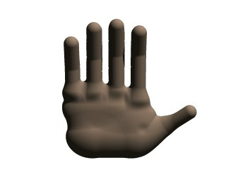
As we can guess from the comments, we are building a hand here. After we render this image, we can see there are a
few problems with it. The palm and heel of the hand would look more realistic if we used a couple dozen smaller
components rather than the half dozen larger ones we have used, and each finger should have three segments instead of
two, but for the sake of a simplified demonstration, we can overlook these points. But there is one thing we really
need to address here: This poor fellow appears to have horrible painful swelling of the joints!
A review of what we know of blobs will quickly reveal what went wrong. The joints are places where the blob
components overlap, therefore the combined strength of both components at that point causes the surface to extend
further out, since it stays over the threshold longer. To fix this, what we need are components corresponding to the
overlap region which have a negative strength to counteract part of the combined field strength. We add the following
components to our blob.
sphere{<-.65,.28,-.05>, .26, -1} //counteract pinky knucklebulge
sphere{<-.65,-.28,0>, .26, -1}   //counteract pinky palm bulge
sphere{<-.3,.44,-.05>, .26, -1}  //counteract ring knuckle bulge
sphere{<-.3,-.28,0>, .26, -1}    //counteract ring palm bulge
sphere{<.05,.49,-.05>, .26, -1}  //counteract middle knuckle bulge
sphere{<.05,-.28,0>, .26, -1}    //counteract middle palm bulge
sphere{<.4,.512,-.05>, .26, -1}  //counteract index knuckle bulge
sphere{<.4,-.4,0>, .26, -1}      //counteract index palm bulge
sphere{<.85,-.68,-.05>, .25, -1} //counteract thumb knuckle bulge
sphere{<.41,-.7,0>, .25, -.89}   //counteract thumb heel bulge
Much better! The negative strength of the spherical components counteracts approximately half of the field strength
at the points where to components overlap, so the ugly, unrealistic (and painful looking) bulging is cut out making
our hand considerably improved. While we could probably make a yet more realistic hand with a couple dozen additional
components, what we get this time is a considerable improvement. Any by now, we have enough basic knowledge of blob
mechanics to make a wide array of smooth, flowing organic shapes!
|
|


