|
 |
1.3.1.5 Bicubic Patch Object
Bicubic patches are useful surface representations because they allow an easy definition of surfaces using only a
few control points. The control points serve to determine the shape of the patch. Instead of defining the vertices of
triangles, we simply give the coordinates of the control points. A single patch has 16 control points, one at each
corner, and the rest positioned to divide the patch into smaller sections. POV-Ray does not ray trace the patches
directly, they are approximated using triangles as described in the Scene
Description Language section.
Bicubic patches are almost always created by using a third party modeler, but for this tutorial we will manipulate
them by hand. Modelers that support Bicubic patches and export to POV-Ray can be found in the links
collection on our server
Let's set up a basic scene and start exploring the Bicubic patch.
#version 3.5;
global_settings {assumed_gamma 1.0}
background {rgb <1,0.9,0.9>}
camera {location <1.6,5,-6> look_at <1.5,0,1.5> angle 40}
light_source {<500,500,-500> rgb 1 }

#declare B11=<0,0,3>; #declare B12=<1,0,3>; //
#declare B13=<2,0,3>; #declare B14=<3,0,3>; // row 1

#declare B21=<0,0,2>; #declare B22=<1,0,2>; //
#declare B23=<2,0,2>; #declare B24=<3,0,2>; // row 2

#declare B31=<0,0,1>; #declare B32=<1,0,1>; //
#declare B33=<2,0,1>; #declare B34=<3,0,1>; // row 3

#declare B41=<0,0,0>; #declare B42=<1,0,0>; //
#declare B43=<2,0,0>; #declare B44=<3,0,0>; // row 4

bicubic_patch {
   type 1 flatness 0.001
   u_steps 4 v_steps 4
   uv_vectors
   <0,0> <1,0> <1,1> <0,1>
   B11, B12, B13, B14
   B21, B22, B23, B24
   B31, B32, B33, B34
   B41, B42, B43, B44
   uv_mapping
   texture {
      pigment {
         checker
         color rgbf <1,1,1,0.5>
         color rgbf <0,0,1,0.7>
         scale 1/3
      }
      finish {phong 0.6 phong_size 20}
   }
   no_shadow
}
The points B11, B14, B41, B44 are the corner points of the patch. All other points are control points. The names of
the declared points are as follows: B for the colour of the patch, the first digit gives the row number, the second
digit the column number. If you render the above scene, you will get a blue & white checkered square, not very
exciting. First we will add some spheres to make the control points visible. As we do not want to type the code for 16
spheres, we will use an array and a while loop to construct the spheres.
#declare Points=array[16]{
   B11, B12, B13, B14
   B21, B22, B23, B24
   B31, B32, B33, B34
   B41, B42, B43, B44
}
#declare I=0;
#while (I<16)
   sphere {
      Points[I],0.1
      no_shadow
      pigment{
         #if (I=0|I=3|I=12|I=15)
            color rgb <1,0,0>
         #else
            color rgb <0,1,1>
         #end
      }
   }
   #declare I=I+1;
#end
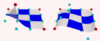
Rendering this scene will show the patch with its corner points in red and its control points in cyan. Now it is
time to start exploring.
Change B41 to <-1,0,0> and render.
Change B41 to <-1,1,0>
and render.
Change B41 to < 1,2,1> and render.
Let's do some exercise with the control points. Start with a flat patch again.
Change B42 to <1,2,0>
and B43 to <2,-2,0> and render.
Change B42 and B43 back to their original positions and try B34
to <4,2,1> and B24 to <2,-2,2> and render. Move the points around some more,
also try the control points in the middle.

After all this we notice two things:
-
The patch always goes through the corner points.
-
In most situations the patch does not go through the control points.
Now go back to our spline work shop and have a look at the bezier_spline again. Indeed, the points B11,B12,B13,B14,
make up a bezier_spline. So do the points B11,B21,B31,B41 and B41,B42,B43,B44 and B14,B24,B34,B44.
So far we have only been looking at one single patch, but one of the strengths of the Bicubic patch lays in the
fact that they can be connected smoothly, to form bigger shapes. The process of connecting is relatively simple as
there are actually only two rules to follow. It can be done by using a well set up set of macros or by using a
modeler. To give an idea what is needed we will do a simple example by hand.
First put the patch in our scene back to its flat position. Then change #declare B14 = <3,0,3>;
#declare B24 = <3,2,2>; #declare B34 = <3.5,1,1> ; #declare B44 = <3,-1,0>; #declare B41 =
<0,-1,0>; Move the camera a bit back camera { location <3.1,7,-8> look_at <3,-2,1.5>
angle 40 } and delete all the code for the spheres. We will now try and stitch a patch to the right side of the
current one. Off course the points on the left side (column 1) of the new patch have to be in the same position as the
points on the right side (column 4) of the blue one.
Render the scene, including our new patch:
#declare R11=B14; #declare R12=<4,0,3>;     //
#declare R13=<5,0,3>; #declare R14=<6,0,3>; // row 1

#declare R21=B24; #declare R22=<4,0,2>;     //
#declare R23=<5,0,2>; #declare R24=<6,0,2>; // row 2

#declare R31=B34; #declare R32=<4,0,1>;     //
#declare R33=<5,0,1>; #declare R34=<6,0,1>; // row 3

#declare R41=B44; #declare R42=<4,0,0>;     //
#declare R43=<5,0,0>; #declare R44=<6,0,0>; // row 4

bicubic_patch {
   type 1 flatness 0.001
   u_steps 4 v_steps 4
   uv_vectors
   <0,0> <1,0> <1,1> <0,1>
   R11, R12, R13, R14
   R21, R22, R23, R24
   R31, R32, R33, R34
   R41, R42, R43, R44
   uv_mapping
   texture {
      pigment {
         checker
         color rgbf <1,1,1,0.5>
         color rgbf <1,0,0,0.7>
         scale 1/3
      }
      finish {phong 0.6 phong_size 20}
   }
   no_shadow
}
This is a rather disappointing result. The patches are connected, but not exactly smooth. In connecting patches the
same principles apply as for connecting two 2D bezier splines as we see in the spline
workshop. Control point, connection point and the next control point should be on one line to give a smooth
result. Also it is preferred, not required, that the distances from both control points to the connection point are
the same. For the Bicubic patch we have to do the same, for all connection points involved in the joint. So, in our
case, the following points should be on one line:
-
B13, B14=R11, R12
-
B23, B24=R21, R22
-
B33, B34=R31, R32
-
B43, B44=R41, R42
To achieve this we do:
#declare R12=B14+(B14-B13);
#declare R22=B24+(B24-B23);
#declare R32=B34+(B34-B33);
#declare R42=B44+(B44-B43);

This renders a smooth surface. Adding a third patch in front is relative simple now:
#declare G11=B41;      #declare G12=B42;                //
#declare G13=B43;      #declare G14=B44;                // row 1

#declare G21=B41+(B41-B31); #declare G22=B42+(B42-B32); //
#declare G23=B43+(B43-B33); #declare G24=B44+(B44-B34); // row 2

#declare G31=<0,0,-2>; #declare G32=<1,0,-2>;           //
#declare G33=<2,0,-2>; #declare G34=<3,2,-2>;           // row 3

#declare G41=<0,0,-3>; #declare G42=<1,0,-3>;           //
#declare G43=<2,0,-3>; #declare G44=<3,0,-3>            // row 4

bicubic_patch {
   type 1 flatness 0.001
   u_steps 4 v_steps 4
   uv_vectors
   <0,0> <1,0> <1,1> <0,1>
   G11, G12, G13, G14
   G21, G22, G23, G24
   G31, G32, G33, G34
   G41, G42, G43, G44
   uv_mapping
   texture {
      pigment {
         checker
         color rgbf <1,1,1,0.5>
         color rgbf <0,1,0,0.7>
         scale 1/3
      }
      finish {phong 0.6 phong_size 20}
   }
   no_shadow
}
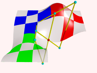
Finally, let's put a few spheres back in the scene and add some cylinders to visualize what is going on. See what
happens if you move for example B44, B43, B33 or B34.
#declare Points=array[8]{B33,B34,R32,B43,B44,R42,G23,G24}
#declare I=0;
#while (I<8)
   sphere {
      Points[I],0.1
      no_shadow
      pigment{
         #if (I=4)
            color rgb <1,0,0>
         #else
            color rgb <0,1,1>
         #end
      }
   }
   #declare I=I+1;
#end
union {
   cylinder {B33,B34,0.04} cylinder {B34,R32,0.04}
   cylinder {B43,B44,0.04} cylinder {B44,R42,0.04}
   cylinder {G23,G24,0.04}
   cylinder {B33,B43,0.04} cylinder {B43,G23,0.04}
   cylinder {B34,B44,0.04} cylinder {B44,G24,0.04}
   cylinder {R32,R42,0.04}
   no_shadow
   pigment {color rgb <1,1,0>}
}
The hard part in using the Bicubic patch is not in connecting several patches. The difficulty is keeping control
over the shape you want to build. As patches are added, in order to keep the result smooth, control over the position
of many points gets restrained.

|
 |


