|
The warp statement is a pattern modifier that is similar to turbulence. Turbulence works by taking the
pattern evaluation point and pushing it about in a series of random steps. However warps push the point in very
well-defined, non-random, geometric ways. The warp statement also overcomes some limitations of
traditional turbulence and transformations by giving the user more control over the order in which turbulence,
transformation and warp modifiers are applied to the pattern.
Currently there are seven types of warps but the syntax was designed to allow future expansion. The turbulence warp
provides an alternative way to specify turbulence. The others modify the pattern in geometric ways.
The syntax for using a warp statement is:
WARP:
    warp { WARP_ITEM }
WARP_ITEM:
    repeat <Direction> [REPEAT_ITEMS...] |
    black_hole <Location>, Radius [BLACK_HOLE_ITEMS...] |
    turbulence <Amount> [TURB_ITEMS...]
    cylindrical  [ orientation VECTOR | dist_exp FLOAT ]
    spherical  [ orientation VECTOR | dist_exp FLOAT ]
    toroidal  [ orientation VECTOR | dist_exp FLOAT |
                major_radius FLOAT ]
    planar [ VECTOR , FLOAT ]
REPEAT_ITEMS:
    offset <Amount> |
    flip <Axis>
BLACK_HOLE_ITEMS:
    strength Strength | falloff Amount | inverse |
    repeat <Repeat> | turbulence <Amount>
TURB_ITEMS:
    octaves Count | omega Amount | lambda Amount
You may have as many separate warp statements as you like in each pattern. The placement of warp statements
relative to other modifiers such as color_map or turbulence is not important. However
placement of warp statements relative to each other and to transformations is significant. Multiple warps and
transformations are evaluated in the order in which you specify them. For example if you translate, then warp or warp,
then translate, the results can be different.
A black_hole warp is so named because of its similarity to real black holes. Just like the real thing,
you cannot actually see a black hole. The only way to detect its presence is by the effect it has on things that
surround it.
Take, for example, a wood grain. Using POV-Ray's normal turbulence and other texture modifier functions, you can
get a nice, random appearance to the grain. But in its randomness it is regular - it is regularly random! Adding a
black hole allows you to create a localized disturbance in a wood grain in either one or multiple locations. The black
hole can have the effect of either sucking the surrounding texture into itself (like the real thing) or pushing
it away. In the latter case, applied to a wood grain, it would look to the viewer as if there were a knothole in the
wood. In this text we use a wood grain regularly as an example, because it is ideally suitable to explaining black
holes. However, black holes may in fact be used with any texture or pattern. The effect that the black hole has on the
texture can be specified. By default, it sucks with the strength calculated exponentially (inverse-square).
You can change this if you like.
Black holes may be used anywhere a warp is permitted. The syntax is:
BLACK_HOLE_WARP:
    warp
    {
        black_hole <Location>, Radius
        [BLACK_HOLE_ITEMS...]
    }
BLACK_HOLE_ITEMS:
    strength Strength | falloff Amount | inverse | type Type |
    repeat <Repeat> | turbulence <Amount>
The minimal requirement is the black_hole keyword followed by a vector <Location>
followed by a comma and a float Radius. Black holes effect all points within the spherical
region around the location and within the radius. This is optionally followed by any number of other keywords which
control how the texture is warped.
The falloff keyword may be used with a float value to specify the power by which the effect of the
black hole falls off. The default is two. The force of the black hole at any given point, before applying the strength
modifier, is as follows.
First, convert the distance from the point to the center to a proportion (0 to 1) that the point is from the edge
of the black hole. A point on the perimeter of the black hole will be 0.0; a point at the center will be 1.0; a point
exactly halfway will be 0.5, and so forth. Mentally you can consider this to be a closeness factor. A closeness of 1.0
is as close as you can get to the center (i.e. at the center), a closeness of 0.0 is as far away as you can get from
the center and still be inside the black hole and a closeness of 0.5 means the point is exactly halfway between the
two.
Call this value c. Raise c to the power specified in falloff. By default Falloff is 2, so this is c^2
or c squared. The resulting value is the force of the black hole at that exact location and is used, after applying
the strength scaling factor as described below, to determine how much the point is perturbed in space.
For example, if c is 0.5 the force is 0.5^2 or 0.25. If c is 0.25 the force is 0.125. But if c is exactly 1.0 the
force is 1.0. Recall that as c gets smaller the point is farther from the center of the black hole. Using the default
power of 2, you can see that as c reduces, the force reduces exponentially in an inverse-square relationship. Put in
plain English, it means that the force is much stronger (by a power of two) towards the center than it is at the
outside.
By increasing falloff, you can increase the magnitude of the falloff. A large value will mean points
towards the perimeter will hardly be affected at all and points towards the center will be affected strongly. A value
of 1.0 for falloff will mean that the effect is linear. A point that is exactly halfway to the center of
the black hole will be affected by a force of exactly 0.5. A value of falloff of less than one but
greater than zero means that as you get closer to the outside, the force increases rather than decreases. This can
have some uses but there is a side effect. Recall that the effect of a black hole ceases outside its perimeter. This
means that points just within the perimeter will be affected strongly and those just outside not at all. This would
lead to a visible border, shaped as a sphere. A value for falloff of 0 would mean that the force would
be 1.0 for all points within the black hole, since any number larger 0 raised to the power of 0 is 1.0.
The strength keyword may be specified with a float value to give you a bit more control over how much
a point is perturbed by the black hole. Basically, the force of the black hole (as determined above) is multiplied by
the value of strength, which defaults to 1.0. If you set strength to 0.5, for example, all points within
the black hole will be moved by only half as much as they would have been. If you set it to 2.0 they will be moved
twice as much.
There is a rider to the latter example, though - the movement is clipped to a maximum of the original distance from
the center. That is to say, a point that is 0.75 units from the center may only be moved by a maximum of 0.75 units
either towards the center or away from it, regardless of the value of strength. The result of this
clipping is that you will have an exclusion area near the center of the black hole where all points whose final force
value exceeded or equaled 1.0 were moved by a fixed amount.
If the inverse keyword is specified then the points pushed away from the center instead of
being pulled in.
The repeat keyword followed by a vector, allows you to simulate the effect of many black holes without
having to explicitly declare them. Repeat is a vector that tells POV-Ray to use this black hole at multiple locations.
Using repeat logically divides your scene up into cubes, the first being located at <0,0,0> and
going to <Repeat>. Suppose your repeat vector was <1,5,2>. The first cube would be
from <0,0,0> to < 1,5,2>. This cube repeats, so there would be one at < -1,-5,-2>, <1,5,2>,
<2,10,4> and so forth in all directions, ad infinitum.
When you use repeat, the center of the black hole does not specify an absolute location in your scene
but an offset into each block. It is only possible to use positive offsets. Negative values will produce undefined
results.
Suppose your center was <0.5,1,0.25> and the repeat vector is <2,2,2>. This gives us a block at <
0,0,0> and <2,2,2>, etc. The centers of the black hole's for these blocks would be <0,0,0> + <
0.5,1.0,0.25>, i. e. <0.5,1.0,0.25>, and < 2,2,2> + <0.5,1.0,0.25>, i. e. < 2,5,3.0,2.25>.
Due to the way repeats are calculated internally, there is a restriction on the values you specify for the repeat
vector. Basically, each black hole must be totally enclosed within each block (or cube), with no part crossing into a
neighboring one. This means that, for each of the x, y and z dimensions, the offset of the center may not be less than
the radius, and the repeat value for that dimension must be >=the center plus the radius since any other values
would allow the black hole to cross a boundary. Put another way, for each of x, y and z
Radius <= Offset or Center <= Repeat - Radius.
If the repeat vector in any dimension is too small to fit this criteria, it will be increased and a warning message
issued. If the center is less than the radius it will also be moved but no message will be issued.
Note that none of the above should be read to mean that you cannot overlap black holes. You most certainly can and
in fact this can produce some most useful effects. The restriction only applies to elements of the same
black hole which is repeating. You can declare a second black hole that also repeats and its elements can quite
happily overlap the first and causing the appropriate interactions. It is legal for the repeat value for any dimension
to be 0, meaning that POV-Ray will not repeat the black hole in that direction.
The turbulence can only be used in a black hole with repeat. It allows an element of
randomness to be inserted into the way the black holes repeat, to cause a more natural look. A good example would be
an array of knotholes in wood - it would look rather artificial if each knothole were an exact distance from the
previous.
The turbulence vector is a measurement that is added to each individual black hole in an array, after
each axis of the vector is multiplied by a different random amount ranging from 0 to 1. The resulting actual position
of the black hole's center for that particular repeat element is random (but consistent, so renders will be
repeatable) and somewhere within the above coordinates. There is a rider on the use of turbulence, which basically is
the same as that of the repeat vector. You cannot specify a value which would cause a black hole to potentially cross
outside of its particular block.
In summary: For each of x, y and z the offset of the center must be >=radius and the value of the repeat must be
>= center + radius + turbulence. The exception being that repeat may be 0 for any dimension, which means do not
repeat in that direction.
Some examples are given by
  warp {
    black_hole <0, 0, 0>, 0.5
  }
  warp {
    black_hole <0.15, 0.125, 0>, 0.5
    falloff 7
    strength 1.0
    repeat <1.25, 1.25, 0>
    turbulence <0.25, 0.25, 0>
    inverse
  }
  warp {
    black_hole <0, 0, 0>, 1.0
    falloff 2
    strength 2
    inverse
  }
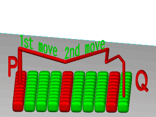
The repeat warp causes a section of the pattern to be repeated over and over. It takes a slice out of
the pattern and makes multiple copies of it side-by-side. The warp has many uses but was originally designed to make
it easy to model wood veneer textures. Veneer is made by taking very thin slices from a log and placing them
side-by-side on some other backing material. You see side-by-side nearly identical ring patterns but each will be a
slice perhaps 1/32th of an inch deeper.
The syntax for a repeat warp is
REPEAT_WARP:
    warp { repeat <Direction> [REPEAT_ITEMS...] }
REPEAT_ITEMS:
    offset <Amount> | flip <Axis>
The repeat vector specifies the direction in which the pattern repeats and the width of the repeated
area. This vector must lie entirely along an axis. In other words, two of its three components must be 0. For example
  pigment {
    wood
    warp { repeat 2*x }
  }
which means that from x=0 to x=2 you get whatever the pattern usually is. But from x=2 to x=4 you get the same
thing exactly shifted two units over in the x-direction. To evaluate it you simply take the x-coordinate modulo 2.
Unfortunately you get exact duplicates which is not very realistic. The optional offset vector tells how
much to translate the pattern each time it repeats. For example
  pigment {
    wood
    warp {repeat x*2  offset z*0.05}
  }
means that we slice the first copy from x=0 to x=2 at z=0 but at x=2 to x=4 we offset to z=0.05. In the 4 to 6
interval we slice at z=0.10. At the n-th copy we slice at 0.05 n z. Thus each copy is slightly different. There are no
restrictions on the offset vector.
Finally the flip vector causes the pattern to be
flipped or mirrored every other copy of the pattern. The first copy of the pattern in the positive direction from the
axis is not flipped. The next farther is, the next is not, etc. The flip vector is a three component x, y, z vector
but each component is treated as a boolean value that tells if you should or should not flip along a given axis. For
example
  pigment {
    wood
    warp {repeat 2*x  flip <1,1,0>}
  }
means that every other copy of the pattern will be mirrored about the x- and y- axis but not the z-axis. A non-zero
value means flip and zero means do not flip about that axis. The magnitude of the values in the flip vector does not
matter.
2.5.12.6.3 Turbulence versus Turbulence Warp
The POV-Ray language contains an ambiguity and limitation on the way you specify turbulence and
transformations such as translate, rotate, scale, matrix, and transform
transforms. Usually the turbulence is done first. Then all translate, rotate, scale, matrix, and transform operations
are always done after turbulence regardless of the order in which you specify them. For example this
 pigment {
   wood
   scale .5
   turbulence .2
 }
works exactly the same as
 pigment {
   wood
   turbulence .2
   scale .5
 }
The turbulence is always first. A better example of this limitation is with uneven turbulence and rotations.
  pigment {
    wood
    turbulence 0.5*y
    rotate z*60
  }
  // as compared to
  pigment {
   wood
   rotate z*60
   turbulence 0.5*y
  }
The results will be the same either way even though you would think it should look different.
We cannot change this basic behavior in POV-Ray now because lots of scenes would potentially render differently if
suddenly the order transformation vs. turbulence mattered when in the past, it did not.
However, by specifying our turbulence inside warp statement you tell POV-Ray that the order in which turbulence,
transformations and other warps are applied is significant. Here is an example of a turbulence warp.
warp { turbulence <0,1,1> octaves 3 lambda 1.5 omega 0.3 }
The significance is that this
 pigment {
   wood
   translate <1,2,3> rotate x*45 scale 2
   warp { turbulence <0,1,1> octaves 3 lambda 1.5 omega 0.3 }
 }
produces different results than this...
 pigment {
   wood
   warp { turbulence <0,1,1> octaves 3 lambda 1.5 omega 0.3 }
   translate <1,2,3> rotate x*45 scale 2
 }
You may specify turbulence without using a warp statement. However you cannot control the order in which they are
evaluated unless you put them in a warp.
The evaluation rules are as follows:
-
First any turbulence not inside a warp statement is applied regardless of the order in which it appears relative
to warps or transformations.
-
Next each warp statement, translate, rotate, scale or matrix one-by-one, is applied in the order the user
specifies. If you want turbulence done in a specific order, you simply specify it inside a warp in the proper place.
Inside the warp statement, the keyword turbulence followed by a float or vector may be
used to stir up any pigment, normal or density. A number of optional parameters
may be used with turbulence to control how it is computed. The syntax is:
TURBULENCE_ITEM:
    turbulence <Amount> | octaves Count |
    omega Amount | lambda Amount
Typical turbulence values range from the default 0.0, which is no turbulence, to 1.0 or more, which is very
turbulent. If a vector is specified different amounts of turbulence are applied in the x-, y- and z-direction. For
example
turbulence <1.0, 0.6, 0.1>
has much turbulence in the x-direction, a moderate amount in the y-direction and a small amount in the z-direction.
Turbulence uses a random noise function called DNoise. This is similar to the noise used in the bozo
pattern except that instead of giving a single value it gives a direction. You can think of it as the direction that
the wind is blowing at that spot. Points close together generate almost the same value but points far apart are
randomly different.
Turbulence uses DNoise to push a point around in several steps called octaves. We locate the
point we want to evaluate, then push it around a bit using turbulence to get to a different point then look up the
color or pattern of the new point.
It says in effect "Do not give me the color at this spot... take a few random steps in different
directions and give me that color". Each step is typically half as long as the one before. For example:
The magnitude of these steps is controlled by the turbulence value. There are three additional parameters which
control how turbulence is computed. They are octaves, lambda and omega. Each
is optional. Each is followed by a single float value. Each has no effect when there is no turbulence. Octaves
The octaves keyword may be followed by an integer value to control the number of steps of turbulence
that are computed. Legal values range from 1 to <10. The default value of 6 is a fairly high value; you will not
see much change by setting it to a higher value because the extra steps are too small. Float values are truncated to
integer. Smaller numbers of octaves give a gentler, wavy turbulence and computes faster. Higher octaves create more
jagged or fuzzy turbulence and takes longer to compute. Lambda
The lambda parameter controls how statistically different the random move of an octave is compared to
its previous octave. The default value is 2.0 which is quite random. Values close to lambda 1.0 will straighten out
the randomness of the path in the diagram above. The zig-zag steps in the calculation are in nearly the same
direction. Higher values can look more swirly under some circumstances. Omega
The omega value controls how large each successive octave step is compared to the previous value. Each
successive octave of turbulence is multiplied by the omega value. The default omega 0.5 means that each
octave is 1/2 the size of the previous one. Higher omega values mean that 2nd, 3rd, 4th and up octaves contribute more
turbulence giving a sharper, crinkly look while smaller omegas give a fuzzy kind of turbulence that gets
blurry in places.
Syntax:
  CYLINDRICAL_WARP:
    warp { cylindrical [CYLINDRICAL_ITEMS...]}
  CYLINDRICAL_ITEMS:
    orientation VECTOR | dist_exp FLOAT
  SPHERICAL_WARP:
    warp { spherical [SPHERICAL_ITEMS...]}
  SPHERICAL_ITEMS:
    orientation VECTOR | dist_exp FLOAT
  TOROIDAL_WARP:
    warp { toroidal [TOROIDAL_ITEMS...]}
  TOROIDAL_ITEMS:
    orientation VECTOR | dist_exp FLOAT | major_radius FLOAT
  PLANAR_WARP:
    warp { planar [ VECTOR , FLOAT ]}
With the cylindrical, spherical and toroidal warps you can wrap checkers, bricks and
other patterns around cylinders, spheres, toruses and other objects. In essence, these warps use the same mapping as
the image maps use.
However it does 3D mapping and some concession had to be made on depth. This is controllable by dist_exp
(distance exponent). In the default of 0, imagine a box <0,0> to <1,1> (actually it is <0,0>, <dist^dist_exp,dist^dist_exp>)
stretching to infinity along the orientation vector. The warp takes its points from that box.
For a sphere distance is distance from origin, cylinder is distance from y-axis, torus is distance
from major radius. (or distance is minor radius if you prefer to look at it that way)
Defaults: orientation <0,0,1>
dist_exp 0
major_radius 1
Examples:
   torus {
     1, 0.5
     pigment {
       hexagon
       scale 0.1
       warp {
         toroidal
         orientation y
         dist_exp 1
         major_radius 1
       }
     }
   }
   sphere {
     0,1
     pigment {
       hexagon
       scale <0.5/pi,0.25/pi,1>*0.1
       warp {
         spherical
         orientation y
         dist_exp 1
       }
     }
   }
   cylinder {
     -y, y, 1
     pigment {
       hexagon
       scale <0.5/pi, 1, 1>*0.1
       warp {
         cylindrical
         orientation y
         dist_exp 1
       }
     }
   }
The planar warp was made to make a pattern act like an image_map, of infinite size and can be useful
in combination with other mapping-warps. By default the pigment in the XY-plane is extruded along the Z-axis. The
pigment can be taken from an other plane, by specifying the optional vector (normal of the plane) and float (distance
along the normal). The result, again, is extruded along the Z-axis.
|


